Understanding Bottlenecks in Mining Operations
In many production systems, there may be one or more operational steps that are heavily loaded such that they limit the throughput of the system. In mining these bottlenecks might be very expensive equipment like Shovels or Crushers. The goal of managers is to design and operate their mining processes in such a way that these operational steps are never starved for work. For example, in open pit mining, we have to ensure that a Shovel pick ore from a face is never waiting for a Haul Truck to load the ore into. In underground mining, an underground Crusher always needs to have ore to process in front of it to chew through.
Why Starving a Bottleneck Hurts Throughput
If time is lost at a non-bottleneck operational step due to blocking or starving, this may have little or no impact on the throughput of the system, since there is excess capacity to make up for the loss in time. However, if time is lost at a bottlenecked operation, there is no excess capacity to make up for the loss. This often has a direct impact on both throughput and Work-in-Progress (WIP) inventory.
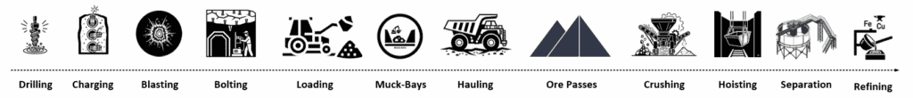
Figure 1 – Example of operational steps in underground mining
Buffer Space Allocation — The Key to Efficiency
This principle states that when allocating limited buffer space to a set of operational steps, it is better to favor the bottlenecked step. This implies not only the bottlenecked step itself, but also any adjacent steps that may block or starve the bottleneck. The optimal allocation of buffer spaces to process steps is a complex algorithm for allocation buffer space but simply states that it is generally better to favor the bottleneck when allocating space.
Testing the principle using MineTwin
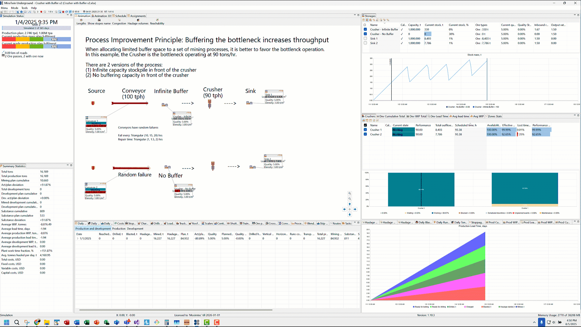
To illustrate our point, we will use MineTwin, a software platform for simulation and planning of mining operations developed by Amalgama. We are using Underground edition that allows us to drag and configure an Ore-pass, a Conveyor, a Crusher and a downstream Storage that acts as our sink. Ore flows from the ore-pass on conveyors at 100 tons per hour. The conveyors are programmed to periodically fail every 10 to 20 hours, taking 1 to 2 hours to be repaired. When the conveyors are down due to failure, ore stops flowing to the Crusher. Crusher operates at a slightly lower rate of 90 tons per hour. Between the conveyor and the crusher is an option to introduce an intermediate Storage element which acts like a buffer.
System 1 — With Buffer
In System 1, we have configured unlimited storage capacity for this buffer. Conveyor unloads ore into this Storage and ore flows out the other end into the Crusher.
System 2 — Without Buffer
In System 2, we have zeroed out the storage capacity of this buffer to simulate a ‘no buffer’ scenario. When conveyor unloads ore into this intermediate Storage, it attempts to flow immediately into the Crusher. Because the crusher’s processing rate (90 tph) is lower than the upstream conveyor (100 tph), the conveyor stops-starts to keep up with the crusher’s rate. This stopping of the conveyor results in lost time.
Additionally, in System 2, when the conveyor is down for failure, the crusher is starved for ore result in lost time and subsequently, lower throughput. This loss cannot be made up in the future when the conveyor comes back online.
Key Findings and Takeaways
This lower throughput of System 2 is evident in both the lower ‘Total outflows’ values for Crusher 2 and final ‘Current Stock’ tonnage of Sink 2 when compared side-by-side with System 1 (Crusher 1 and Sink 1).
The magnitude of starvation at the crusher and lower throughput is a function of the downtime profile of the conveyor (i.e. how often it goes down and for how long?) and buffer capacity upstream from the crusher. There is no excess capacity in System 2 (no buffer between conveyor and crusher) to absorb the variability in ore delivery by the upstream conveyor. This explains why limited buffer space to buffers upstream and downstream from the bottleneck improves the system performance.
In the above flow line example, identifying the upstream and downstream operations is straightforward. However, in a real mining system, ore can flow from multiple stopes and ore passes to a crusher. Nonetheless, the principle still applies: any operational step that sends a significant quantity of ore to the bottlenecked operational step should be considered for buffering.
Contact us to learn how MineTwin can help you identify and eliminate bottlenecks in your mining process.
FAQs
Q: What is a bottleneck in mining operations?
A bottleneck is an operational step that limits the throughput of the entire mining process, such as a crusher or shovel.
Q: How does buffer space improve mining throughput?
Buffer space near bottlenecked equipment absorbs variability in ore delivery, reducing downtime and improving throughput.
Step-by-step instructions for testing in MineTwin
- Download MineTwin Underground
- Simply unzip the file on your computer. No installation required.
- Launch MineTwin by double-clicking “MineTwin Underground.exe”
- Build the flow line simulation
- Once MineTwin opens, navigate to the ‘Home – scenario editor’ tab
- We add 2 ore types to our model using the tree-menu on the left (Scenario -> Ore -> Ore types)
- Using the ‘Ore types’ tab that opens at the bottom, we add 2 rows, one for Ore and other for Waste. For the ‘Ore’ ore type, we set both their Mining type to ‘Production’.
- We add 2 material types using the tree-menu (Scenario -> Ore -> Materials)
- Add 2 rows, one for Ore and other for Waste. The Ore row will set the material type to ‘Substance’ and Waste row has it set to ‘Empty rock’.
- On the ‘Map’ tab, add multiple MineNodes
- MineNodes are single dots in the Map tab
- Connect two of the MineNodes with MineArcs
- Add Ore Pass using the tree-based menu on the left (Scenario -> Material Flow -> Ore passes)
- Call this ore pass: ‘Source’
- Configure the ore pass with a sufficiently large initial quantity of ore, say 1M tons.
- Add a Conveyor using the tree-menu on the left (Scenario -> Material Flow -> Conveyors)
- Call this conveyor: ‘Conveyor’
- Select the newly added conveyor in the ‘Conveyors’ tab that pops up, navigate to the ‘Mine arcs’ section and assign to a Mine Arc to the conveyor
- Set the conveyor’s flow rate to 100 tph
- Add a Storage to represent input buffer to crusher from the tree-menu on the left (Scenario -> Material Flow -> Storage)
- Call this Storage: “Crusher – Input Buffer”
- In the Storage window that is docked at the bottom, configure storage’s Capacity parameter to either 1M tons (System 1) or 1 ton (System 2) depending on you are creating a buffer or no buffer in front of the crusher.
- Add a Crusher from the tree-menu on the left (Scenario -> Material Flow -> Crusher)
- Call this crusher: “Crusher”
- On the newly added crusher, configure it’s Performance parameter to a rate of 90 tph.
- Add another Storage to represent the Sink
- Call this storage: “Sink”
- Now we need to logically connect the storages, conveyor and crusher.
- Click on the “Source” ore pass; in the Properties of the ore pass, click the ‘Connectors’ button and map the input and output MineNode from the layout.
- Click on the “Crusher – Input Buffer” storage;
- set the ‘In flow connector’ to be the previous mine node in your layout i.e. the output node of the conveyor.
- Select the ‘Out flow connector’ dropdown to select the “Crusher” object.
- Click on the “Crusher” object from your project tree on the left and its properties window, set the “Out flow connector” to be the “Sink” storage object. Note: no need to set the in-flow connector as MineTwin already assigns on based on the previous step.
- Add a downtime profile for unplanned failures using the tree menu on the left (Scenario -> Schedules -> Unplanned events)
- In the “Unplanned events” tab on the right, add a row and give it a name “Conveyor failures”
- In the “Unplanned events records” tab on its right, set the ‘Time between events’ to triangular (10, 15, 20) hours and ‘Event duration’ to triangular (1, 1.5, 2) hours.
- In the ‘Applying unplanned events’ window at the bottom, assign this event to the conveyor object.
- Configure the scenario by clicking the top-level node of the tree menu on the left
- In the Properties window that opens at the bottom, click on the ‘General’ button and set the begin date to 1/1/2025 and end date to 1/1/2026 for the simulation.
- In the ‘Scheduling’ tab, set the scheduling mode to ‘By target’.
- Next we add a target plan using the tree-menu on the left (Scenario -> Plans -> Target plan)
- Add a new row in the Plans tab that opens with a Begin date of 1/1/2025, End date of 1/1/2026, Mining type of Production, Quality of 5%, and Planned mass of 1M tons.
- Check the model for errors (click the ‘Check’ button in the ribbon)
- Run the Simulation and note down the throughput
- Click on the ‘Simulate’ button then on the ribbon, hit the play button.
- To fast-forward click on the ‘Fastest’ button in the ribbon.
- Once the simulation is done running, a pop-up notifies you of the run duration being complete.
- Review the various output tables and charts and play with the model inputs.
Credits
- Pegden, C Dennis. Process Improvement Principles. First ed., Simio LLC, 2014.
- Amalgama Software Design, Dubai UAE, MineTwin Underground (1.10.3)